BGP Multicast VPN
Published 2021-12-26
This post assumes the reader has prior knowledge regarding MPLS L3VPN, LDP and PIM. We will be implementing this on JunOS and IOS-XR.
This type of Multicast VPN used to be called Next Generation MVPN or NG-MVPN because it uses BGP signaling instead of PIM signaling between PEs. Previous generations where called Rosen GRE and Rosen mLDP that relied on PE-to-PE PIM adjacencies to signal the multicast state.
One improvement of BGP over PIM between PEs is that an update is only sent once. With PIM, the PEs have to continually update each other on the current state, causing less scalability.
MVPN terminology
- AD = Auto Discovery
- PMSI = Provider Multicast Service Interface. Can be described as a P2MP tunnel/LSP.
- I-PMSI = Inclusive PMSI, similar to PIM Dense Mode. Tunnel leads to all other PEs.
- S-PMSI = Selective PMSI, similar to PIM Sparse Mode. Tunnel leads to a select group of receiver PEs.
Inclusive vs Selective Tunnels
Multicast is a constant battle of bandwidth efficiency and signaling efficiency, you can't have both at the same time. Selective tunnels (S,G) and (*,G) are most efficient in terms of bandwidth since they reach only reach receivers that specifically requested the traffic. Inclusive tunnels (*,*) have very little signaling but often waste bandwidth resources.
BGP MVPN defaults to inclusive tunnels and sends the multicast flows to all MVPN PE neighbors in the L3VPN. Once the bandwidth of a multicast flow exceeds a set threshold, the flow can be moved to a selective tunnel that is signaled separately, allowing specific receiver PEs to join.
BGP MVPN Route Types
The job of BGP MVPN is advertising the multicast routes inside a L3VPN. To get this done, a number of different route types are used. We will focus on Type 1 in this chapter, but each is briefly described here:
Intra-AS I-PMSI Auto Discovery
This is equivalent to a PIM Hello packet. A PE will advertise a Type 1 route to let all other PEs in the L3VPN know that it is available send or receive multicast traffic, essentially joining the inclusive tunnel for this VPN.
Inter-AS I-PMSI Auto Discovery
Same as type 1, but between ASes. We will not cover this here.
S-PMSI Auto Discovery
This route is advertised by the Sender PE, allowing Receiver PEs to choose if they want to receive this particular multicast traffic or not, hence the keyword selective.
Leaf Auto Discovery
This route is advertised by a Receiver PE to the Sender PE of a selective multicast flow when the transport is RSVP, allowing the PE to receive a selective multicast flow. This route type is not necessary when using mLDP as the multicast transport.
Source Active Auto Discovery
Not covered here
C-Multicast Source Tree Join
Not covered here
C-Multiast Shared Tree Join
This route is advertised by a Receiving PE when receiving a downstream PIM Join message from a CE; the route is basically a Join message for a specific (S,G) multicast flow and is targeted to a specific Sender PE. The route does not include any information about who the Receiver PE is. This route is necessary in case the Sender PE wants to send the multicast on an S-PMSI, that way the Sender PE know that alteast one reciever PE is interested in receiving this flow.
For this reason, low bandwidth multicast flows are sent as Inclusive by default. Once the flow bandwidth pass a certain threshold value, the traffic is instead moved to a Selective tunnel.
LDP Transport
This topology uses LDP to MPLS encapsulate the unicast L3VPN traffic and mLDP to MPLS encapsulate the multicast L3VPN traffic. This allows traffic VPN traffic between PEs to travel across the core without the P-nodes having to examine the IP header.
Unicast LDP
Unicast LDP builds Multi-point-to-Point(MP2P) LSPs for each prefix, meaning the same label is advertised to all neighbors. For example, P2 received the loopback prefix 1.1.1.1/32 from PE1. P2 forwards this route to PE3 and P5 with label 111 essentially saying; use this label if you want me to forward traffic to PE1. It doesn't matter if the traffic is received from PE3 or P5, label 111 sends the traffic to PE1. In other words, the MP2P LSP is signaled from the Receiver PE to all Sender PEs.
Multicast LDP (mLDP)
To allow the multicast traffic to flow MPLS-encapsulated across the core network we enable Multicast LDP, mLDP for short. A multicast mLDP LSP is Point-to-Multi-point (P2MP), so the exact opposite of unicast LDP. The P2MP LSP is signaled from every Receiver towards the Source PE.
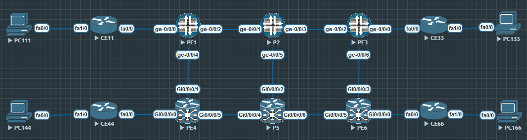
Example Topology
Topology is as shown below. All core links have a metric of 1 except for PE-PE links that have a metric of 10. P2 is also the RR. PC111 is the source of the (10.0.11.111, 232.1.1.1) multicast flow that the other PCs want to receive. All CEs belong to the same VRF-A L3VPN.
mLDP signaling in our example topology
This section looks at how mLDP is used to signal a multicast path from each Receiver PE towards PE1, the Sender PE.
PE1 advertises Type 1 route:
Let's look at an example using the BGP Multicast VPN topology below. Let's look at the BGP route advertised by PE1 when it joins the VRF-A VPN. With this route, PE1 tells the other PE routers in the VPN that it may want to send or receive multicast traffic in the future.
Frame 12: 188 bytes on wire (1504 bits)Internet Protocol Version 4, Src: 1.1.1.1, Dst: 2.2.2.2Border Gateway Protocol - UPDATE Message Path Attribute - MP_REACH_NLRI (AFI): IPv4 (1), (SAFI): MCAST-VPN (5) Intra-AS I-PMSI A-D route (12 bytes) Route Distinguisher: 65000:1 Originating Router: 1.1.1.1 Path Attribute - PMSI_TUNNEL_ATTRIBUTE Type Code: PMSI_TUNNEL_ATTRIBUTE (22) Tunnel Type: mLDP P2MP LSP (2) Tunnel ID: Type: P2MP root node: 1.1.1.1 Id: 16777219The output show the route as a Type 1 Intra-AS I-PMSI A-D. PE1 has assigned the tunnel ID 16777219 and the multicast traffic will be transported in a mLDP LSP. As soon as the other PEs receive this route, they immediately begin signaling a P2MP mLDP LSP towards 1.1.1.1, as shown below.
Receiver PE LDP signaling towards PE1:
The wireshark output below show the LDP signaling along the path from PE4 and PE6 towards PE1. As the output will show; every message contains the same tunnel ID advertised by PE1, but each router along the path generates its own local label.
Internet Protocol Version 4, Src: 6.6.6.6, Dst: 5.5.5.5Label Distribution Protocol Label Mapping Message FEC FEC Element Type: P2MP Root Node Address: 1.1.1.1 Opaque Value: 16777219 Generic Label: 24011Internet Protocol Version 4, Src: 4.4.4.4, Dst: 5.5.5.5Label Distribution Protocol Label Mapping Message FEC FEC Element Type: P2MP Root Node Address: 1.1.1.1 Opaque Value: 16777219 Generic Label: 24000Internet Protocol Version 4, Src: 5.5.5.5 Dst: 2.2.2.2Label Distribution Protocol Label Mapping Message FEC FEC Element Type: P2MP (6) Root Node Address: 1.1.1.1 Opaque Value: 16777219 Generic Label: 24010Internet Protocol Version 4, Src: 2.2.2.2 Dst: 1.1.1.1Label Distribution Protocol Label Mapping Message FEC FEC Element Type: P2MP (6) Root Node Address: 1.1.1.1 Opaque Value: 16777219 Generic Label: 300288 PE3 and PE4 joining the multicast tree:
PE3 and PE4 has not yet sent their mLDP messages. Let's say PE4 send its mLDP message to P5 now. The tunnel ID is the same, 16777219, and PE4 chooses to advertise label 24000 to P5.
When P5 receive the message from PE4, it realizes the tunnel ID is the same as the one signaled by PE6, so no further mLDP messages are sent upstream towards PE1. Instead P5 adds its interface towards PE4 to the list of outgoing interfaces, becoming a brancing point in the multicast tree and replicates the packet, sending one copy to PE6 and one to PE4. This is the MPLS forwarding output on P5:
RP/0/0/CPU0:P5#show mpls forwarding labels 24010Local Outgoing Prefix Outgoing Next Hop Bytes Label Label or ID Interface Switched ------ ----------- ------------------ ------------ --------------- ------------24010 24000 mLDP/IR: 0x0000c Gi0/0/0/4 10.4.5.4 0 24011 mLDP/IR: 0x0000c Gi0/0/0/6 10.5.6.6 0 The same thing happens on P2 when it receives the mLDP message from PE3. The interface towards PE3 is added to the outgoing interface list, no additional signaling towards PE1 is required.
The label path in action:
PC111 start generating multicast traffic that is sent to CE11 which forwards it to PE1. PE1 sends the trafic out on tunnel 16777219 and is forwarded to PE6 like this:
label 300228 label 24010 label 24011 PE1 -------------> P2 -------------------> P5 ------------> PE6 | | +---------------> PE3 +--------------> PE4 label 300240 label 24000Finally PE6 receives the traffic and forwards it to PC133 via CE33.
Configuration
This is the configuration used in this lab.
ip multicast-routinginterface FastEthernet0/0 ip address 10.1.11.11 255.255.255.0 ip pim sparse-modeinterface FastEthernet1/0 ip address 10.0.11.1 255.255.255.0 ip pim sparse-mode ip igmp version 3router bgp 65001 bgp log-neighbor-changes redistribute connected neighbor 10.1.11.1 remote-as 65000no ip pim autorpip pim ssm defaultset security forwarding-options family mpls mode packet-basedset interfaces ge-0/0/0 unit 0 family inet address 10.1.11.1/24set interfaces ge-0/0/2 unit 0 family inet address 10.1.2.1/24set interfaces ge-0/0/2 unit 0 family mplsset interfaces ge-0/0/4 unit 0 family inet address 10.1.4.1/24set interfaces ge-0/0/4 unit 0 family mplsset interfaces lo0 unit 0 family inet address 1.1.1.1/32set routing-instances VRF-A instance-type vrfset routing-instances VRF-A protocols bgp group CE type externalset routing-instances VRF-A protocols bgp group CE peer-as 65001set routing-instances VRF-A protocols bgp group CE as-overrideset routing-instances VRF-A protocols bgp group CE neighbor 10.1.11.11set routing-instances VRF-A protocols mvpnset routing-instances VRF-A protocols pim interface ge-0/0/0.0set routing-instances VRF-A interface ge-0/0/0.0set routing-instances VRF-A route-distinguisher 65000:1set routing-instances VRF-A vrf-target target:65000:1set routing-instances VRF-A vrf-table-labelset routing-instances VRF-A provider-tunnel ldp-p2mpset routing-instances VRF-A provider-tunnel selective group 232.0.0.0/8 source 0.0.0.0/0 ldp-p2mpset protocols ospf area 0.0.0.0 interface lo0.0 passiveset protocols ospf area 0.0.0.0 interface ge-0/0/2.0 interface-type p2pset protocols ospf area 0.0.0.0 interface ge-0/0/2.0 ldp-synchronizationset protocols ospf area 0.0.0.0 interface ge-0/0/4.0 interface-type p2pset protocols ospf area 0.0.0.0 interface ge-0/0/4.0 metric 10set protocols ospf area 0.0.0.0 interface ge-0/0/4.0 ldp-synchronizationset protocols bgp group PE type internalset protocols bgp group PE local-address 1.1.1.1set protocols bgp group PE family inet-vpn unicastset protocols bgp group PE family inet-mvpn signalingset protocols bgp group PE peer-as 65000set protocols bgp group PE mvpn-iana-rt-importset protocols bgp group PE neighbor 3.3.3.3set protocols bgp group PE neighbor 4.4.4.4set protocols bgp group PE neighbor 6.6.6.6set protocols igmp interface ge-0/0/0.0 version 3set protocols ldp interface ge-0/0/2.0set protocols ldp interface ge-0/0/4.0set protocols ldp p2mpset protocols mpls interface ge-0/0/2.0set protocols mpls interface ge-0/0/4.0set routing-options autonomous-system 65000hostname PE4domain lookup disablevrf VRF-A address-family ipv4 unicast import route-target 65000:1 export route-target 65000:1line console width 128 length 0!interface Loopback0 ipv4 address 4.4.4.4 255.255.255.255!interface MgmtEth0/0/CPU0/0 shutdown!interface GigabitEthernet0/0/0/0 vrf VRF-A ipv4 address 10.4.44.4 255.255.255.0!interface GigabitEthernet0/0/0/1 ipv4 address 10.1.4.4 255.255.255.0!interface GigabitEthernet0/0/0/2 shutdown!interface GigabitEthernet0/0/0/3 shutdown!interface GigabitEthernet0/0/0/4 shutdown!interface GigabitEthernet0/0/0/5 ipv4 address 10.4.5.4 255.255.255.0!route-policy MLDP set core-tree mldp-defaultend-policy!router ospf 1 log adjacency changes mpls ldp sync mpls ldp auto-config address-family ipv4 area 0 interface Loopback0 passive enable ! interface GigabitEthernet0/0/0/1 cost 10 network point-to-point ! interface GigabitEthernet0/0/0/5 network point-to-point ! !!router bgp 65000 bgp router-id 4.4.4.4 address-family vpnv4 unicast ! address-family ipv4 mvpn ! neighbor-group PE remote-as 65000 update-source Loopback0 address-family vpnv4 unicast ! address-family ipv4 mvpn ! ! neighbor 1.1.1.1 use neighbor-group PE ! neighbor 3.3.3.3 use neighbor-group PE ! neighbor 6.6.6.6 use neighbor-group PE ! vrf VRF-A rd 65000:1 bgp unsafe-ebgp-policy address-family ipv4 unicast redistribute connected ! address-family ipv4 mvpn ! neighbor 10.4.44.44 remote-as 65001 address-family ipv4 unicast as-override ! ! !!mpls ldp mldp ! interface GigabitEthernet0/0/0/1 ! interface GigabitEthernet0/0/0/5 !!multicast-routing address-family ipv4 interface Loopback0 enable ! mdt source Loopback0 mdt mldp in-band-signaling ipv4 ! vrf VRF-A address-family ipv4 interface GigabitEthernet0/0/0/0 enable ! bgp auto-discovery mldp ! mdt default mldp p2mp ! !!router pim vrf VRF-A address-family ipv4 rpf topology route-policy MLDP mdt c-multicast-routing bgp ! interface GigabitEthernet0/0/0/0 enable ! ! !!end